SC/Tetra is a versatile computational fluid dynamics (CFD) software designed for precise thermo-fluid analysis. It utilizes a hybrid mesh system to accurately represent complex geometries, ensuring high-precision simulations. SC/Tetra excels in handling complex fluid dynamics scenarios, making it an essential tool for industries ranging from automotive to aerospace, such as turbulent flows, heat transfer, and aerodynamic noise. With features like automatic mesh generation, overset mesh, and fluid-structure interaction, SC/Tetra delivers powerful performance while maintaining user-friendly operation.
scFLOW is a cutting-edge Computational Fluid Dynamics (CFD) software developed by Software Cradle, designed to deliver advanced simulation capabilities with a user-friendly interface. scFLOW offers enhanced stability and speed, making it ideal for engineers and researchers aiming to simulate complex fluid dynamics scenarios. scFLOW’s innovative features, such as a new solver, polyhedral mesher, and enhanced CAD data handling, ensure precise and efficient analysis, making it a preferred choice for professionals in the field of thermo-fluid analysis.
Product Brochure – Cradle CFD
Download a PDF brochure on thermo-fluid analysis software developed and provided by Software Cradle.
File Type: PDF – [1.34 MB]
Get in touch
Your inquiry will be replied by local representative, which may take up to 24 business hours.
We may not be able to provide answers to some inquiries.
Features
SC/Tetra is a general-purpose thermo-fluid analysis (CFD) software that utilizes hybrid mesh to achieve the best representation of surface geometry with high precision. Its features include an automatic detailed mesh generation system, high-speed computing (HPC), low memory (RAM) usage, and a user-friendly graphical user interface (GUI) throughout the software operation.
Program Structure
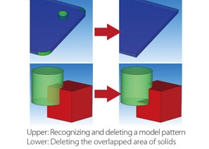
CAD Modification
When CAD data intended for simulation encounters a problem, it can be modified within the Preprocessor of SC/Tetra. Boundary conditions can be set based on part names and color data from the CAD software. If certain areas, including surfaces or entire parts, are missing from the model, shapes such as surfaces, cuboids, and cylinders can be created directly within SC/Tetra.
Mesh-adaptation analysis
This function allows the mesh to be automatically refined in areas where there are significant differences in flow or heat during a steady-state analysis. After the Solver completes the calculation, the Preprocessor automatically relaunches and re-executes gridding and meshing based on the previous simulation results. By setting the target number of mesh elements, a coarse mesh is initially created, and then the mesh is automatically refined to suit the calculation needs. This function is particularly useful for analyzing flows in complex models with intricate shapes.
Discontinuous mesh
This function enables automatic mesh refinement in areas with significant differences in flow or heat during a steady-state analysis. After the Solver completes the calculation, the Preprocessor automatically relaunches, executing gridding and meshing based on the previous simulation results. By setting a target number of mesh elements, a coarse mesh is initially created, followed by automatic refinement to achieve the optimal fit for the calculation. This function is particularly useful for analyzing flows in complex models with intricate shapes.
Overset mesh
Regions with free motion, which cannot be simulated using existing functions such as stretching or rotating parts, can now be analyzed by intersecting mesh elements for both stationary and moving regions. This function supports the overlap of multiple moving regions, contact between part models, and 6-degree-of-freedom (6DOF) movements of rigid parts. It is particularly useful for simulating phenomena such as the opening and closing of a pump valve in an engine port or the interaction of gears in a gear pump.
Modifying CAFree surface (steady-state / transient)D data
The shape of an interface between gas and liquid phases can be observed using the VOF method. Currently, a new method called “FIRM” is available, offering both fast and precise calculations. Features such as translating or rotating boundaries, overset mesh, and particle tracking can be utilized simultaneously. Because phenomena where each phase interface becomes stable can be simulated in a steady-state calculation, results can be obtained in a shorter time than with previous versions.
*Note: Only scFLOW supports the FIRM method.
6-degree-of-freedom motion (6DOF)
Passive motions, such as translation and rotation of a rigid part caused by fluid forces, can be simulated. With this function, users can observe a ball valve with a focus on the elasticity of the spring in 1-Dimensional translation, as well as a paper airplane considering 6-degree-of-freedom (6DOF) rigid-body movements, including 3-Dimensional translation and 3-Dimensional rotation simultaneously. Additionally, this feature is also utilized in the analysis of operating check valves, wind turbine generators, and rotating blades of wave power generators.
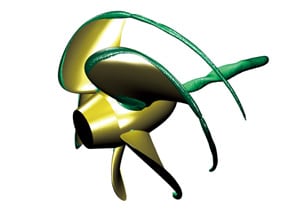
Cavitation
This function allows the simulation of cavitation, a vaporization phenomenon that occurs in areas where liquid pressure drops below that of the surrounding environment, such as with a propeller rotating at full speed underwater. Cavitation can be simulated by applying the cavitation model in SC/Tetra, based on pressure values. The software also enables users to identify issues caused by cavitation, such as erosion.
Fluid-structure interaction
scFLOW now supports the free movement of regions, which cannot be analyzed using existing functions, such as stretching or rotating elements, by overlapping mesh elements for stationary and moving regions. This function supports the overlap of multiple moving regions, contact between objects, and 6-degree-of-freedom motion of rigid bodies. It is particularly useful for analyzing the opening and closing of a valve in an engine port or the engagement of gears in a gear pump.
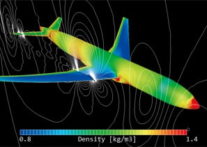
Compressible fluid
The software can simulate behaviors such as supersonic flow and significant volume expansion or contraction. For compressible fluids, both pressure-based and density-based CFD solvers can be utilized. The density-based solver maintains calculation stability even at high Mach numbers. You can choose the appropriate solver depending on the simulation target and the specific behavior being analyzed.
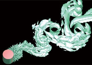
Aerodynamic noise analysis
Sound generated from pressure vibrations in a fluid, such as wind noise, and sound from resonance can be simulated. Precise calculations can be achieved by applying LES (Large-Eddy Simulation) and the weak compressible flow model. The frequency of aerodynamic sound can also be analyzed using the Fast Fourier Transform (FFT) method in SC/Tetra.
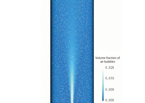
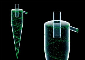
Dispersed multi-phase flow
This function can predict flows containing various fluid features such as bubbles, droplets, or particles (dispersed phase), which are challenging to simulate using the free surface method. It utilizes a multi-fluid model that simulates the volume fraction and velocity distribution of each phase by solving the governing equations under the assumption that the dispersed phase is within a continuous fluid phase. This function is particularly useful for simulating the bubble jet effect and aeration tanks.
Particle tracking
This function can predict flows containing various fluid features such as bubbles, droplets, or particles (dispersed phase), which are challenging to simulate using the free surface method. It utilizes a multi-fluid model that simulates the volume fraction and velocity distribution of each phase by solving the governing equations under the assumption that the dispersed phase is within a continuous fluid phase. This function is particularly useful for simulating the bubble jet effect and aeration tanks.
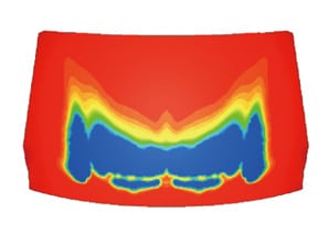
Humidity dew condensation
The amount of dew condensation on a surface can be calculated based on the surface temperature and water vapor in the air. In a steady-state analysis, the amount of dew condensation per unit time can be output, while in a transient analysis, the accumulated dew condensation can be calculated. Additionally, evaporation from the surface where dew condensation occurs can be analyzed simultaneously, making this particularly useful for analyzing windshield defrosters.
Liquid film model
The liquid film model is an extension of the particle tracking function. With this model, users can simulate the phenomenon where liquid particles form a liquid film (such as water on a wall) upon reaching the surface. A liquid film on a wall flows under the influence of gravity and gas-phase flow, depending on the wall’s angle, and collects at certain positions. The analysis results are output as the thickness of the liquid film.
Thermoregulation-model (JOS)
scFLOW can simulate flows containing numerous bubbles, droplets, or particles (dispersed phase), which are challenging to analyze using the free surface method. This multi-fluid model predicts the volume fraction distribution and velocity distribution of each phase by solving the governing equations under the assumption that the dispersed phase behaves as a fluid (continuous phase). This function is particularly useful for analyzing bubble jet effects and aeration tanks.
LES
The combined use of the thermoregulation model (JOS) and fluid analysis allows for the simulation of the surface temperature of a human body in a specific thermal environment. It can also be used to analyze temperature and humidity changes in the surrounding environment. Users can account for factors such as age, clothing, and physiological phenomena like heat transfer through blood flow, in addition to environmental factors such as temperature and air velocity.
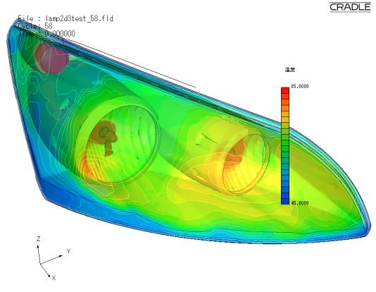
Radiation
Heat transfer by infrared radiation can be analyzed by setting the emissivity and temperature difference between objects. Users can choose between the VF (View Factor) method or the FLUX method for calculations. Additionally, they can consider factors such as wavelength dependence, transmission, absorption, refraction, diffusion, and reflection of radiation. The FLUX method also allows for the consideration of directionality.
Mapping
When a target phenomenon occurs within a small range but is influenced by a wider surrounding area, the analysis results of the surrounding area can be used as boundary conditions for the target phenomenon. This approach helps to decrease the overall calculation load.
Fan model (rotating blades)
With this model, the average flow field around rotating blades can be simulated by simply entering characteristic properties, without needing the actual shapes of fans or propellers. Users can utilize the non-dimensional swirl coefficient model, the simplified propeller model, and the simplified rotor model. This model is particularly useful for analyzing axial-flow windmills and waterwheels.
Coupled analysis with GT-SUITE
Coupled analysis with GT-SUITE is available, allowing the entire flow in an intake and exhaust system to be calculated with GT-SUITE, while small flows within each part are interpolated using scFLOW or SC/Tetra. This approach enhances the calculation accuracy of the entire system.
SmartBlades
This function is useful for automatically analyzing the shape of a fan, from creating the fan’s shape (CAD data) to calculating the flow and post-processing. The fan shape can be easily generated by specifying parameters such as the number of blades, fan diameter, rake angle, and skew angle.
Functions for turbomachinery
SC/Tetra offers specialized functions for turbomachinery analysis, tailored to simulate the unique flow characteristics within rotating machinery, such as pumps, compressors, and turbines. These features include advanced blade row modeling and automatic mesh generation for complex geometries, allowing precise analysis of fluid dynamics, including vortex shedding and pressure distribution. The software also supports multi-reference frame (MRF) and sliding mesh techniques, enabling accurate simulations of interactions between rotating and stationary components.
FluidBearingDesigner
This function creates groove patterns for fluid bearings (dynamic-pressure bearings) and generates the corresponding mesh. You can select groove shapes, such as journal and thrust, as well as materials, including porous options. From the calculation results, you can obtain key design parameters for fluid bearings, such as axial force and drag coefficient.