How to model air filter in scSTREAM is a fundamental skill for any CFD engineer working with ventilation, HVAC, or airflow-critical systems. Whether you’re designing cleanrooms, automotive cabins, or electronic enclosures, simulating air filters accurately is essential to predict Pressure loss, Airflow Behavior, and Thermal Performance. In this guide, you’ll learn how to set up filter modeling in scSTREAM using real data, Input Coefficients, and Validation Techniques—ensuring both efficiency and accuracy in your simulation workflow.
In this comprehensive guide, we’ll walk you through How to Model Air Filters in scSTREAM, a powerful simulation tool by Hexagon. We’ll walk you through how to model air filter in scSTREAM step-by-step—from geometry setup and Cf/N input to pressure loss validation and post-processing visualization.
Table of Contents
🔍 What is a Filter in CFD?
To understand how to model air filter in scSTREAM, it helps to first grasp how filters are represented in CFD—as porous media that resists airflow based on physical properties like thickness, fiber density, and layering. Instead of modeling each microscopic fiber, we use equivalent resistance coefficients that mimic the filter’s effect on airflow.
In scSTREAM, this is done by:
- Creating a solid region representing the filter
- Assigning porous media properties using resistance coefficients
- Defining flow direction and boundary conditions around it
🎯 The goal is to simulate pressure loss and velocity drop accurately without overcomplicating the geometry.
Before diving into the geometry setup, let’s briefly highlight why how to model air filter in scSTREAM is especially relevant in industrial airflow applications.
🧱 Step 1: Prepare the Geometry and Set the Condition Region
To start modeling an air filter in scSTREAM, create a solid geometry block that defines the physical filter region in your airflow simulation.
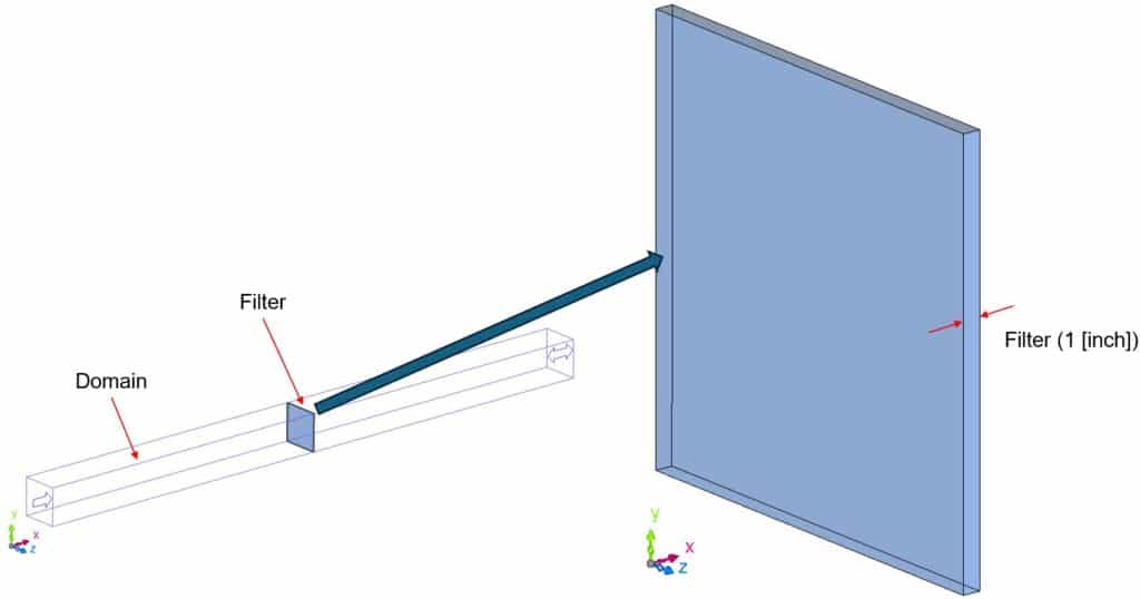
- 🧩 Create a block or plate positioned exactly where the filter exists in your physical system (e.g., within a duct or HVAC unit).
- 🧱 This filter block should be separate from the rest of the geometry to allow specific settings to be applied.
- ⚙️ Once created, change the attribute of this geometry to “Condition Region”. This is essential, as the pressure loss will be applied to this region—not through material properties.
Source: Hexagon Simcompanion
💡 Using a condition region makes it possible to define pressure loss using input parameters Cf and N, which are directly linked to test data.
🔧 Quick Tips:
- ✅ The thickness of the filter block should match the real-world filter thickness (if known).
- 🎯 To get accurate results when learning how to model air filter in scSTREAM, make sure the filter is aligned perpendicular to the airflow direction for accurate modeling.
- ❌ Avoid leaving small gaps between the filter and adjacent walls unless intentional (e.g., simulating bypass leakage).
One of the most important parts of how to model air filter in scSTREAM is applying the correct pressure loss coefficients.
⚙️ Step 2: Assign Porous Media Properties
Certainly! Here’s the rewritten Step 2 that accurately reflects the original article’s instruction to set the volumetric pressure loss condition via the Condition Wizard in scSTREAM:
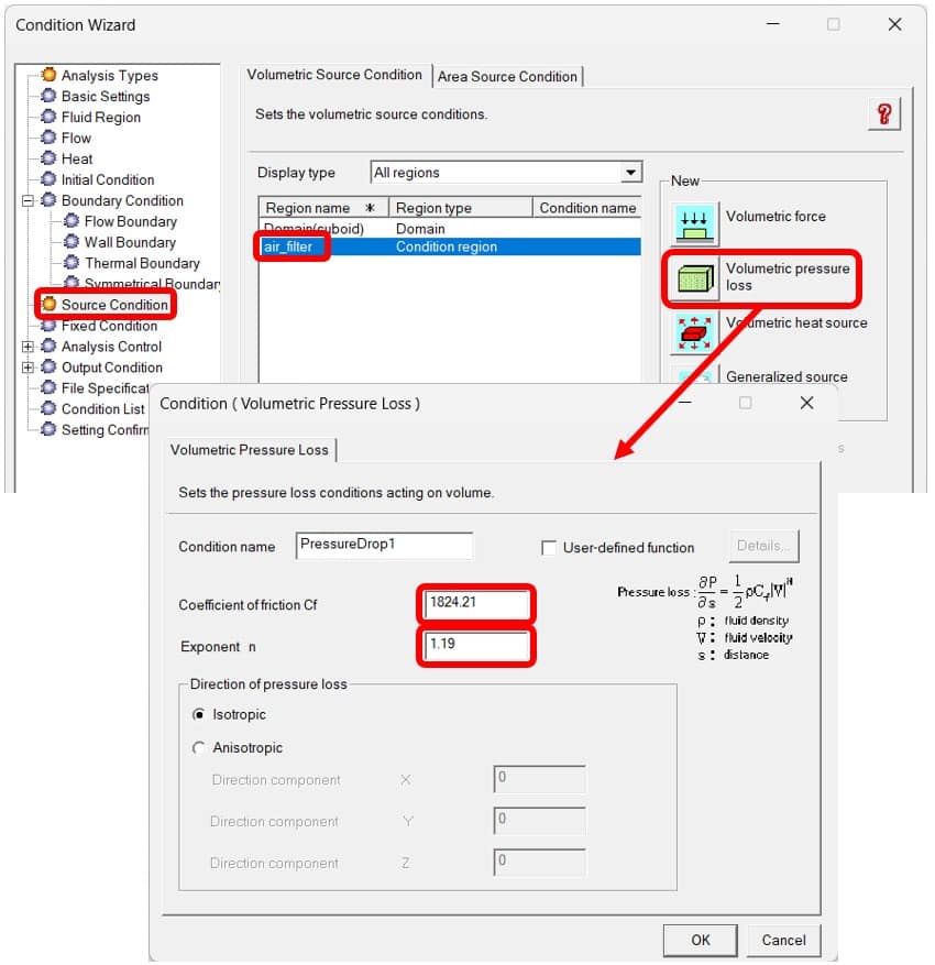
In scSTREAM, this is done using the Volumetric Pressure Loss setting under the Condition Wizard.
🧭 How to Set It:
- Open the Condition Wizard.
- Navigate to Source Condition.
- Select Volumetric Pressure Loss from the list.
- Enter the values for:
- Cf (Viscous Resistance Coefficient) — corresponds to K in Darcy’s Law
- N (Inertial Resistance Coefficient) — corresponds to C in the Forchheimer term
These values are derived from pressure loss vs. velocity data, often provided by the air filter manufacturer or calculated from experimental curves (explained in Step 3).
✏️ Example:
Cf = 2.3 × 10^9 [1/m²]
N = 1.2 × 10^5 [1/m]
These values can be obtained by:
- 📄 Manufacturer datasheets
- 📈 Fitting pressure drop vs. velocity curve
- 🧪 Experimental test data
🧠 The higher the values, the more restrictive the filter is to flow.
📌 Note: scSTREAM calculates pressure loss per unit length, so ensure units are converted properly when using test data based on total pressure drop.
💡 This air filter modeling method in scSTREAM also applies to thin porous components like mesh screens, HEPA filters, or ventilation fins.
👉 “Learn more about setting advanced conditions in our Comprehensive Guide to scSTREAM Scripting“
🌪 Step 3: Set Up Boundary Conditions
To simulate airflow across the filter realistically:
- Inlet ➤ Set velocity or volumetric/mass flow rate
- Outlet ➤ Set static pressure or gauge pressure = 0 Pa
- Optional ➤ Add symmetry or wall boundaries on sides if ducted
💬 If turbulence is expected downstream, enable a turbulence model like k-ε or SST.
📐 Step 4: Mesh the Filter Region Properly
Porous media works best when mesh resolution across the filter is adequate:
- Use 3–5 cells through the thickness of the filter
- Avoid overly coarse mesh or distorted cells
✅ This ensures proper calculation of pressure gradient and velocity drop across the filter.
💻 Step 5: Run the Simulation
Once your domain, mesh, materials, and boundaries are ready—run the solver.
Observe:
- Pressure contours upstream and downstream of the filter
- Streamlines to detect flow disruption or recirculation zones
- Velocity profiles through the filter plane
🔍 You should see a clear drop in static pressure and velocity attenuation post-filter.
📊 Bonus: Verifying Pressure Loss
The pressure drop across a filter in scSTREAM should match theoretical or experimental expectations.
Use the simplified pressure loss equation:
ΔP = Cf ⋅ μ ⋅ v + N ⋅ ½ ⋅ ρ ⋅ v²
Where:
- ΔP = pressure drop
- Cf = viscous resistance coefficient [1/m²]
- N = inertial resistance coefficient [1/m]
- μ = dynamic viscosity of air
- ρ = air density
- v = velocity through the filter
These values (Cf and N) are input directly in the Material Settings under Porous Media.
📌 Compare the result with lab data or datasheets to validate accuracy.
🧠 Optional: Particle Tracking for Filtration Efficiency
In advanced setups, you may want to evaluate filtration performance by tracking particles (dust, pollen, etc.) through the domain.
scSTREAM supports:
- Lagrangian particle tracking
- Deposition models
- Filtration rate estimations
This helps evaluate:
- Particle retention vs. penetration
- Clogging behavior (in multi-step analyses)
📎 Use Case Applications
Understanding how to model air filter in scSTREAM has broad applications across multiple industries:
- 🚗 Automotive (Cabin air filters)
- 🏢 HVAC (Ventilation ducts, HEPA filters)
- 📦 Consumer Electronics (Cooling fans with mesh filters)
- 🧪 Cleanroom design (Laminar airflow with filtration)
✅ Pre-Run Checklist
Here’s a quick list to double-check before running your simulation:
🔲 Geometry includes filter as a separate part
🔲 Porous media is assigned with correct K and C
🔲 Boundary conditions are correctly applied
🔲 Mesh quality is validated across the filter
🔲 Pressure drop matches estimated/calculated range
🔲 Post-processing fields are selected
👉 “Looking for more examples of how to model airflow and filters in scSTREAM? Check out our Case Study: Improving Thermal Comfort in Thailand with scSTREAM.”
References
- Hexagon SimCompanion – How to model air filter in scSTREAM — Describes the step‑by‑step process of creating a filter block, setting it as a condition region, applying volumetric pressure loss, extracting Cf and N from test data, and validating results simcompanion.hexagon.com.